Table of Contents
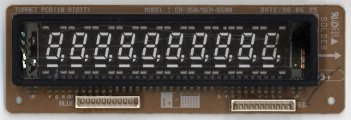
The firefly conductor is a vacuum fluorescent display (VFD) driver/controller.
Main parts:
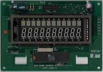
- the VFD has been salvaged from a Samsung SER6540II cash register.
- it came with Supertex HV518 VFD chips to drive the individual segments of the display.
- I use a STM32F103 micro-controller to control the display.
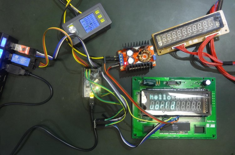
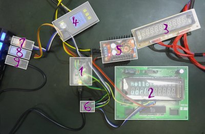
setup
- STM32F1 development board, based on a STM32F103C8T6 micro-controller (32-bit ARM Cortex M3, 72MHz)
- the main VFD I salvaged from a Samsung SER6540II cash register (cashier side)
- the secondary VFD I salvaged from a Samsung SER6540II cash register (customer side). this one is broken though.
- main power supply
- adjustable boost converter to drive the VFD
- level shifter to connect the 3.3V STM32 signals to the 5V HV518 pins
- USB to UART converter (SiLabs CP2102 based) to communicate with the micro-controller
- SWD adapter (ST-Link v2 clone) to flash the micro-controller
- USB to power (providing 5V), flash (using DFU), and communicate with (using CDC ACM) the micro-controller
VFD
introduction
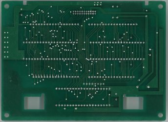
The SER6500 VFD comes with 3 Supertex HV518 VFD drivers (2 are hidden behind the display).
They each can driver 32 channels (up to 90V). The VFD segments start already to be visible at 5V, but to get them bright you need higher voltages (I use 50V). This is particularly important because you have to drive the digits and matrix one after each other. If you do it fast enough, thanks to the persistence of vision they will not appear as flickering. But because the segments are not on all the time, you need to drive them with higher voltage so on average they appear bright enough. I drive the VFD with 60V and use a 100 Hz refresh rate.
The VFD has 10 digits (7+3 segments) and 12 dot matrix (7×5 segments). You would need 10*(7+3)+12*(5*7)=520 pins to drive each segment individuals. That's far too many. This is why they are multiplexed. One pin drives the same segment across all digits (or matrix). And you can select which digits/matrix you want to drive individuals. Thus is you want to display different text on the digits/matrix, you first drive the grid for this digits/matrix (and only this), drive the segment for this character, and then you do the same for all others (one after each other). That leaves us with 10+(7+3)+12+(5*5)=57 pins. And this is also why 3 VFD drivers are need, because each can only control up to 32 channels.
HV518
Controlling them is pretty easy.
You just:
- provide power (5V on the VDD pin)
- send serial data into the built-in shift register (using the DIN and CLK pins)
- latch to output the data in parallel (using the NLE pin)
- enable the output buffers (using the STR pin)
- this drives the 32 high voltage channels (with the voltage provided using the VPP pin)
The drivers also provide a DOUT pin which will relay the serial data. This allows to chains them and shift the 3×32 data bits using a single line (the CLK pin is shared).
pinout
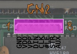 The CN2 connector at the bottom of the SER6500 has the following pinout:
- GND: ground
- VDD: 5V to power the HV518 VFD driver
- VPP: <90V to drive the VFD segments
- DIN: to shift the data in
- CLK: clock to shift the data, on the clock rise
- #LE: enable latch on low (aka. negative LE, or NLE)
- STR: strobe the shifted data
- AUX: connected to ground when the auxiliary display is present
 The CN1 connector at the top of the SER6500 is used to forward the signals to the auxiliary VFD (to display the price for the customer).
The second VFD has 10 digits, and is a copy of the 10 digits from the main VFD (minus comma and underline).
The AUX pin of CN2 is shorted to ground when the auxiliary VFD is connected. You can use the AUX pin to detect if the auxiliary VFD is present by pulling the pin up and checking if it's low (because shorted to ground). You can also the use AUX pin as second ground pin (i.e. for the VPP power suply). If the auxiliary VFD is not present, just short the 3rd right-most top pin with the 2nd right-most bottom pin.
segments
The three HV518 are chained. To control all the VFD segments you just have to shift 3×32 bits.
In the following tables the left-most 32-bit word is transmitted first, with least significant bit (right-most) shift first.
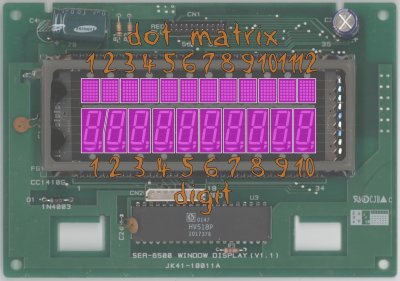 grid selection (for digits and dot matrix)
| hex value (3×32 bits) | word | bit | display type | grid position |
|---|---|---|---|---|
| 00000000 00000008 00000000 | 2 | 4 | matrix | 1 |
| 00000000 00000004 00000000 | 2 | 3 | matrix | 2 |
| 00000000 00000002 00000000 | 2 | 2 | matrix | 3 |
| 00000000 00000001 00000000 | 2 | 1 | matrix | 4 |
| 80000000 00000000 00000000 | 1 | 32 | matrix | 5 |
| 40000000 00000000 00000000 | 1 | 31 | matrix | 6 |
| 20000000 00000000 00000000 | 1 | 30 | matrix | 7 |
| 10000000 00000000 00000000 | 1 | 29 | matrix | 8 |
| 08000000 00000000 00000000 | 1 | 28 | matrix | 9 |
| 04000000 00000000 00000000 | 1 | 27 | matrix | 10 |
| 02000000 00000000 00000000 | 1 | 26 | matrix | 11 |
| 01000000 00000000 00000000 | 1 | 25 | matrix | 12 |
| 00000000 00002000 00000000 | 2 | 14 | digit | 1 |
| 00000000 00001000 00000000 | 2 | 13 | digit | 2 |
| 00000000 00000800 00000000 | 2 | 12 | digit | 3 |
| 00000000 00000400 00000000 | 2 | 11 | digit | 4 |
| 00000000 00000200 00000000 | 2 | 10 | digit | 5 |
| 00000000 00000100 00000000 | 2 | 8 | digit | 6 |
| 00000000 00000080 00000000 | 2 | 8 | digit | 7 |
| 00000000 00000040 00000000 | 2 | 7 | digit | 8 |
| 00000000 00000020 00000000 | 2 | 6 | digit | 9 |
| 00000000 00000010 00000000 | 2 | 5 | digit | 10 |
 grid selection (for digits and dot matrix)
| hex value (3×32 bits) | word | bit | segment |
|---|---|---|---|
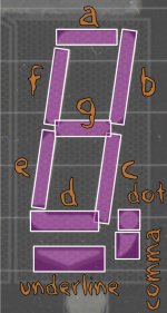
| 00000000 00004000 00000000 | 2 | 15 | underline |
| 00000000 00008000 00000000 | 2 | 16 | dot |
| 00000000 00010000 00000000 | 2 | 17 | comma |
| 00000000 00020000 00000000 | 2 | 18 | a |
| 00000000 00040000 00000000 | 2 | 19 | b |
| 00000000 00080000 00000000 | 2 | 20 | c |
| 00000000 00100000 00000000 | 2 | 21 | d |
| 00000000 00200000 00000000 | 2 | 22 | e |
| 00000000 00400000 00000000 | 2 | 23 | f |
| 00000000 00800000 00000000 | 2 | 24 | g |
 grid selection (for digits and dot matrix)
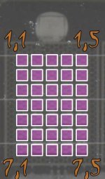
| hex value (3×32 bits) | word | bit | column | row |
|---|---|---|---|---|
| 00000000 01000000 00000000 | 2 | 25 | 1 | 1 |
| 00000000 02000000 00000000 | 2 | 26 | 1 | 2 |
| 00000000 04000000 00000000 | 2 | 27 | 1 | 3 |
| 00000000 08000000 00000000 | 2 | 28 | 1 | 4 |
| 00000000 10000000 00000000 | 2 | 29 | 1 | 5 |
| 00000000 20000000 00000000 | 2 | 30 | 1 | 6 |
| 00000000 40000000 00000000 | 2 | 31 | 1 | 7 |
| 00000000 00000000 00000001 | 3 | 1 | 2 | 1 |
| 00000000 00000000 00000002 | 3 | 2 | 2 | 2 |
| 00000000 00000000 00000004 | 3 | 3 | 2 | 3 |
| 00000000 00000000 00000008 | 3 | 4 | 2 | 4 |
| 00000000 00000000 00000010 | 3 | 5 | 2 | 5 |
| 00000000 00000000 00000020 | 3 | 6 | 2 | 6 |
| 00000000 00000000 00000070 | 3 | 7 | 2 | 7 |
| 00000000 00000000 00000100 | 3 | 9 | 3 | 1 |
| 00000000 00000000 00000200 | 3 | 10 | 3 | 2 |
| 00000000 00000000 00000400 | 3 | 11 | 3 | 3 |
| 00000000 00000000 00000800 | 3 | 12 | 3 | 4 |
| 00000000 00000000 00001000 | 3 | 13 | 3 | 5 |
| 00000000 00000000 00002000 | 3 | 14 | 3 | 6 |
| 00000000 00000000 00004000 | 3 | 15 | 3 | 7 |
| 00000000 00000000 00010000 | 3 | 17 | 4 | 1 |
| 00000000 00000000 00020000 | 3 | 18 | 4 | 2 |
| 00000000 00000000 00040000 | 3 | 19 | 4 | 3 |
| 00000000 00000000 00080000 | 3 | 20 | 4 | 4 |
| 00000000 00000000 00100000 | 3 | 21 | 4 | 5 |
| 00000000 00000000 00200000 | 3 | 22 | 4 | 6 |
| 00000000 00000000 00400000 | 3 | 23 | 4 | 7 |
| 00000000 00000000 01000000 | 3 | 25 | 5 | 1 |
| 00000000 00000000 02000000 | 3 | 26 | 5 | 2 |
| 00000000 00000000 04000000 | 3 | 27 | 5 | 3 |
| 00000000 00000000 08000000 | 3 | 28 | 5 | 4 |
| 00000000 00000000 10000000 | 3 | 29 | 5 | 5 |
| 00000000 00000000 20000000 | 3 | 30 | 5 | 6 |
| 00000000 00000000 40000000 | 3 | 31 | 5 | 7 |
micro-controller
The hardware used to control this VFD is a STM32F1 development board, based on a STM32F103C8T6 micro-controller (32-bit ARM Cortex M3, 72MHz).
The firmware is available here. It :
- starts by testing all segments of the VFD
- plays an animation
- and finally displays the text typed in over the USB CDC ACM or USART1 ports
The data is shifted out from the micro-controller to the drivers using SPI (this protocol fits well what the HV518 requires). A timer will periodically refresh all parts of the VFD at 100 Hz.
Since the STM32 provides only 3.3V I/Os and the HV518 requires 5V signals I used a simple level shifter. But actually it works fine also without, by directly connecting the HV518 to the STM32.
Connection:
| STM32 signal | board pin | VFD CN2 pin | HV518 signal |
|---|---|---|---|
| GND | 1 | GND | |
| 5V | 2 | VDD | |
| 3 | VPP | ||
| SPI1_MOSI | PA7 | 4 | DIN |
| SPI1_SCK | PA5 | 5 | CLK |
| GPIO | PA4 | 6 | NLE |
| GPIO | PA6 | 7 | STR |
| 8 | AUX |
The VPP and GND pins to drive the VFD segments are provided using an external power supply. I use a boost converter and set it to 50V.

