Table of Contents
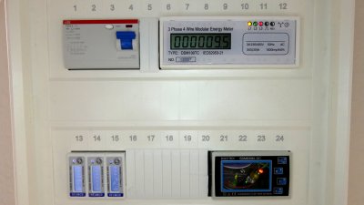
The spark abacus is a custom electricity meter monitoring system. It's a follow-up of the spark counter, but for a 3-phase 4-wire mains electricity power distribution installation.
It is composed by:
- 1 DDM100TC 3-phase 4-wire electricity meter with pulse output
- 3 SDM120 single phase electricity meter with Modbus interface (with an UART to RS-485 adapter)
- 3 PZEM-004T single phase electricity meter with UART interface
- 1 STM32F1 micro-controller to collect the measurements from the electricity meters
- 1 ESP6266 WiFi module to transmit the measurement values to the database
- 1 Orange Pi PC single board computer with InfluxDB time series database and Grafana graphical monitoring tool
prototypes
complete
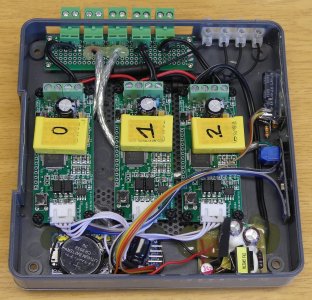
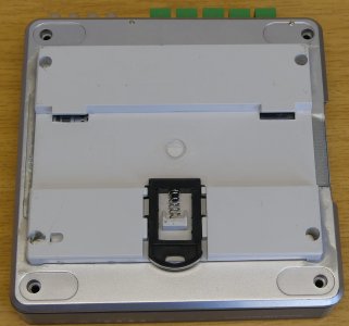
The first prototype used an old WiFi D-Link router case. I glued a DIN-rail mount on the back to install it in the distribution panel. The development board is a small blue pill.
I could fit all elements inside, including the three PZEM-004Ts, and had nice connectors, but it was too large to fit in the distribution panel along with the other electricity meters and RCCB.
The source code and all technical details are available on git.
light
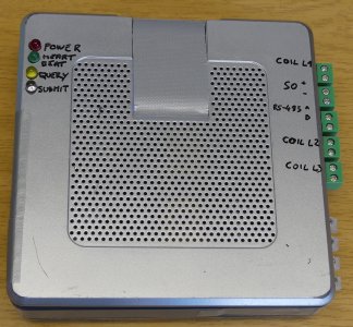
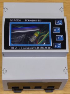
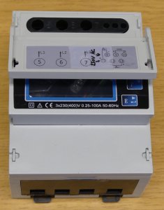
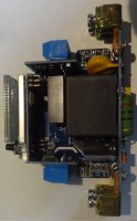
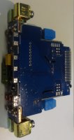
For this second prototype I used a broken SDM630 electricity meter case. It is smaller and is designed to fit nicely in the distribution panel.
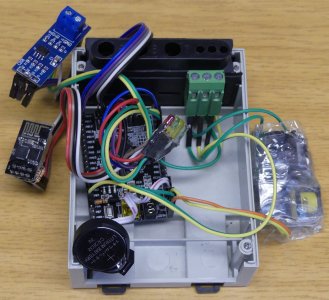
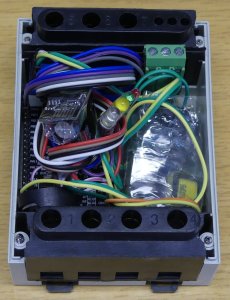
This time I did not include the PZEM-004T meters since they are to large to fit in, and would only provide information I could already get from the other electricity meters. This left a lot of space to include a larger development board, and I could use dupont cables to connect all elements. I used the connector already available in the case (for two pulse outputs and one RS-485 interface) as inputs for the monitoring system (one pulse input, as RS-485 master, AC input for 5V).
The source code and all technical details are available on git.
improvements
Future improvments:
- submit measurement values to influxDB using UDP (faster, no need for credentials)
- make a bulk ModBus request to get most measurements at once (the pauses between requests for each measurement cost a lot of time)
- use an LCD to show the values (the LEDs only show the status)
- use the touch button already available on the SDM630 case
electricity meters
For the spark abacus I am using several electricity meters. This just evolved over time as I wanted to try different technologies, but one (set) of them is sufficient to complete the task.
peacefair PZEM-004T
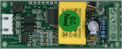
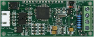
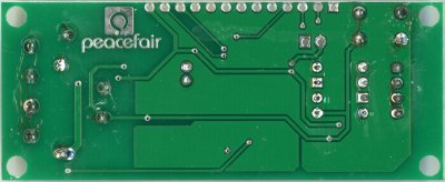
The pacefair PZEM-004T is an inexpensive single phase electricity meter.
Connect mains electricity (AC) and the current sensing coil (put around the wire going to the load to monitor) and this electricity meter will measure voltage, current, power (active), and energy used by the load to monitor. The energy value is saved (in EEPROM) and can be reset using the button (on the board).
The device also offers a serial port (isolated from mains electricity using optocouplers) so to be able to read out the measured values. The serial protocol is the same as for the PZEM-004.
Compared to the PZEM-004 it comes without display and buzzer, but is much smaller. Else it uses the same design and chip.
DDM100TC
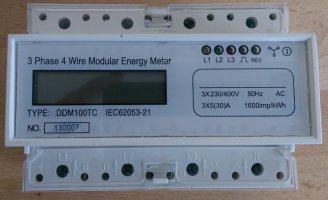
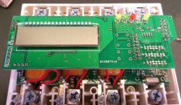
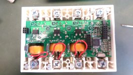
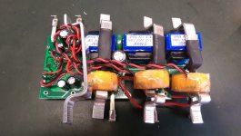
The DDM100TC (you can find it under different brands) is a 3-phase 4-wire electricity meter.
The meter provides:
- 1 LCD to show the energy used in kWh (with a precision od 0.1 kWh)
- 3 LEDs to show which phase powered (L1, L2, L3)
- 1 LED to show the direction to the current (reverse if REV is on)
- 1 LED to show impulses as energy is used
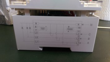
- 1 S0 interface to output impulses as energy is used
The S0 interface (labelled TEST on the side) allows me to collect the energy used on my micro-controller. Connect the + side (pin 8) to a positive voltage (i.e. +5V), an the - side (pin 7) to an input (with a pull-down resistor). Each impulse will generate a high signal (+2.5V in my case) on - for ~ 90 ms. The number of impulses indicates the energy used, and the time interval between impulses indicates the current power consumption. I chose one with a high impulse rate of 1600 impulses/kWh (= 1 impulse for every 0.625 Wh).
There is also the DDM100TCR model with an RS-485 interface, but I couldn't find any documentation about the protocol messages, thus I wasn't interested in this feature.
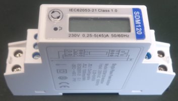
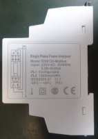
Eastron SDM120-Modbus
The Eastron SDM120-Modbus is a slim 1-phase 2-wire electricity meter.
Be aware as numerous SDM120 models exist, combining following options:
- in-line current measurement or using a current sensing coil (CT)
- with electro-mechanical display or LCD, sometimes with backlight
- only with 2 pulse outputs, or with additional MBus or Modbus interface
I chose the SDM120 model (one per phase) since I wanted to learn about the RS-485 interface and Modbus protocol. The corresponding Modbus document (older v2.1) lists the registers containing the measurements (input registers) and configuration (holding registers). This document also explains the Modbus protocol, but I rather recommend to read the one for the SDM630 since it contains more information, most importantly the timing between messages.
ESP8266
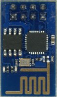
To send the values measured by the electricity meters and collected by the micro-controller, I used a WiFi module based on the ESP8266 SoC.
Several modules based on this chip exist. Since I only use its WiFi functionality, and no other micro-controller capability, I used the simplest, smallest, and cheapest one, the ESP-01.
ESP-01
To use the device, simply connect GND, VCC (3.3V), RX (module input), TX (module output), RST (using a pull-up resistor), and CH_PD (using a pull-up resistor).
AT firmware
My module showed the following firmware information when powered up (with 9600 8N1 serial configuration): Vendor:www.ai-thinker.com Version:0.9.2.4.
When using the AT+GMR command to get the version it showed 0018000902-AI03.
This custom firmware wasn't particularly stable, so I decided to use a more recent, and standard one.
To flash a firmware you have to enter the bootloader mode by connecting GPIO0 to ground. Then you can use one of the numerous ESP flashing tools. I used esptool.
Espressif offers SDKs for the ESP chips. Since I only want to use this module for its WiFi connectivity I only care about the AT firmware. The AT firmware allows to control the ESP using AT commands over serial. This firmware is provided in the NONOS SDKs (V2.0.0 as of 2016-08-10).
The module I had uses a 25Q40 flash chip with only 4Mbits/512KBytes. You can also identity using esptool:
esptool --port /dev/ttyUSB0 flash_id

esptool.py v1.1
Connecting...
Manufacturer: c8
Device: 4013
As mentioned in the SDK notes: “Since the release of ESP8266_NONOS_SDK_V1.5.0, AT firmware is too large to use 4Mbit flash. Please choose flash with at least 8Mbit capacity.”
This is mainly because it is now possible to update the firmware over the air, thus there needs to be a second firmware image the main firmware can write and boot.
I was still able to flash the AT firmware provided in SDK 1.5.0 from 2015-11-27 (archive) using the “non-boot” version as described in the readme.txt:
cd esp_iot_sdk_v1.5.0/bin/at/
esptool --port /dev/ttyUSB0 write_flash 0x00000 noboot/eagle.flash.bin 0x40000 noboot/eagle.irom0text.bin 0x7e000 ../blank.bin 0x3e000 ../blank.bin
esptool.py v1.1
Connecting...
Running Cesanta flasher stub...
Flash params set to 0x0000
Writing 28672 @ 0x0... 28672 (100 %)
Wrote 28672 bytes at 0x0 in 2.5 seconds (92.0 kbit/s)...
Writing 249856 @ 0x40000... 249856 (100 %)
Wrote 249856 bytes at 0x40000 in 21.7 seconds (92.3 kbit/s)...
Writing 4096 @ 0x7e000... 4096 (100 %)
Wrote 4096 bytes at 0x7e000 in 0.4 seconds (90.5 kbit/s)...
Writing 4096 @ 0x3e000... 4096 (100 %)
Wrote 4096 bytes at 0x3e000 in 0.4 seconds (90.5 kbit/s)...
Leaving...
Now when I ask for the firmware version using the AT+GMR command (with 115200 8N1 serial configuration) I get the following:
AT version:0.51.0.0(Nov 27 2015 13:37:21)
SDK version:1.5.0
compile time:Nov 27 2015 13:57:56
OK
Here is also the AT v0.51 Instruction Set for SDK v1.5 (archive).
I wasn't able to get AT firmware from later SDKs (>1.5.0) to work though. But again, this is just if you have only 4 Mbits (512KBytes) of flash. It is now also possible to get ESP-01 modules with 8 Mbits / 1 MByte of flash, which supports more recent AT firmwares.
Orange Pi PC
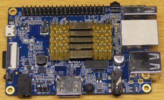
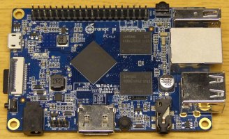
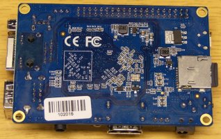
The Orange Pi PC is a cheap $15 alternative to the Raspberry Pi 2. This single board computer (SBC) is based on an Allwinner H3 (sun8iw7p1) SoC with ARM Cortex-A7 @ 1.2GHz (often over-clocked), and 1 GB of RAM.
For this price the hardware is unbeatable, but the software support is really poor. Also only Android supports the video hardware acceleration currently. The official images are quite old (e.g. Android 4.2.2), but there are a bit newer images made available by the community:
- Android (often ROMs from other Allwinner based products), with a weird installation process
- various linux distributions
Since I'll only use it as server I decided to go with an armbian debian jessie image.
The pin header is the same as the 40-pin Raspberry Pi, but seeing the support of the OS I wouldn't rely on the hardware drivers. I am only using this SBC a cheap computer rather than hardware platform. Also, don't forget to put a heat sink on the CPU, else they will be slowed down quite often because of the high temperatures.
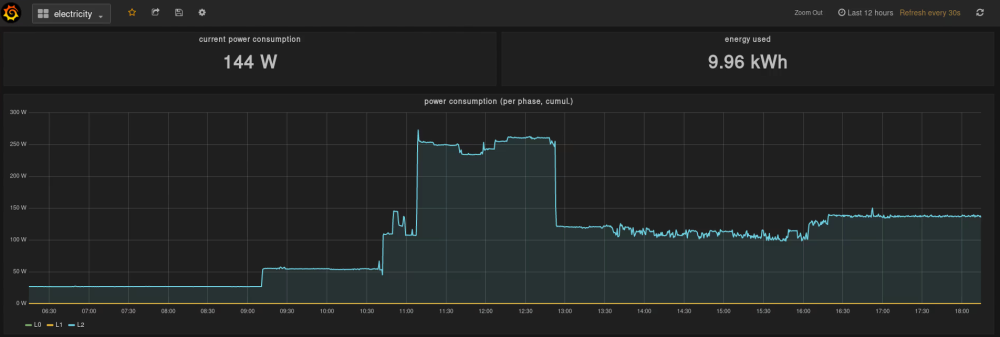
On it I've installed an InfluxDB time-series database to store the values (using the HTTP API), and Grafana to visualize them.

