Table of Contents
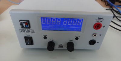
This article is about measuring the accuracy on the EA PS 2084-03 B power supply.
acquisition
Until then I used and ATX power supply with an ATX breakout board. I provides all voltages needed for electronics: 3.3 V, 5 V, and 12 V. But you can't set the current. It only comes with a 1.25 A polyfuse.
So I decided it was time to buy my first bench power supply. But is had to fulfil the following criteria:
- set voltage and current
- wide voltage range (0-50 V)
- silent
- have an earth connection
- not expensive
- not noname
- provide a communication interface (most important)
I found and bought a used power supply on eBay for ~ 80 €. And now I own an Elektro-Automatik EA-PS 2084-03 B power supply. And this fulfilled are the requirements:
- set voltage and current: in 0.1 V and 0.01 A steps
- wide voltage range (0-50 V): 0-84 V, 0-3 A (not a lot, but enough for electronics), limited to 100 W
- silent: no fan, full passive cooling
- have an earth connection: on the front panel
- not expensive: ~ 80 €
- not noname: Elektro-Automatik (never heard of it, but it's German and they have a decent website)
- provide a communication interface: USB with proprietary documented protocol
Here some more documents about this power supply:
- driver (USB ACM for Windows)
- easyPS2000 software (Windows, demo version)
measurement
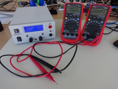
When powering the device on, I noticed that the voltage on the display did not change while I was turning on the knob. But the Digital Multi-Meter (DMM) actually shows that the voltage actually does change. Just the reading on the screen is inaccurate.
It was time to measure how inaccurate this power supply is. But doing that manually just takes to long. So I decided to implement the protocol to control the the power supply, and I will measure the set output using a DMM connected to the computer.
power supply
To control the power supply I implemented the protocol described in the programming manual. The source code is available on git.
The control programming will increment the voltage from 0 to 84 V in 0.1 V steps, at 1.0 A. It will set the voltage and current which are set, actual (measured by the power supply), and measured (measured by the DMM)
Using this script I could also find the following undocumented objects (for commands): 80, 81, 82, 83, 84, 85, 86, 87, 88, 149, 150, 151, 152, 156, 158, 160, 161, 162. These probably allow you to flash the firmware or calibrate the power supply.
multimeter
To measure the output of the power supply I used two UNI-T UT61E. These are good multimeters for electronics which you can get quite cheap, with 22000 counts, and a connection to the PC. More functions and its accuracy are available in the manual (archive).
connection
UT-D02
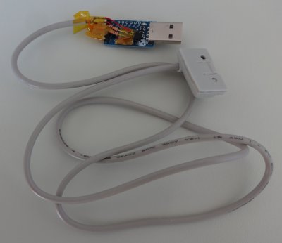
The DMM comes with an RS232 UT-D02 cable. To connect to the PC you need a RS232 to USB converter (are PCs with COM ports still manufactured?).
The cheapest RS232 to USB converter one is based on the CH341 chip. Sadly the 7O1 mode used by the multimeter isn't supported by the linux driver. I also tried the patch, and after toggling DTR I get wrong data out.
I also has an old ARL3116 based RS232 to USB converter, but there too the mode didn't seem to be supported.
Finally I found a FT232-based RS232 to USB converter. This is an expensive cable (but good quality), from an evil company, and it worked.
Here is the schematic of this cable:
But instead of using it, I decided to connect the cable to a CP2102-based UART to USB converter. Then you have to keep two things in mind:
- RS232 signals are between -12 to +12 V, while UART uses 0-5 V. This was solved by simply using the 5 V pin from the converter to power the cable.
- RS232 signals are inverted compared to UART. This was solved by inverting the signal using an NPN transistor and two resistors.
| UT-D02 wire | CP2102 UART signal | PNP |
|---|---|---|
| green | GND | |
| yellow | GND | |
| orange | 5V | |
| GND | E | |
| 5V + 10kΩ | C | |
| brown + 10kΩ | B | |
| RX | C |
UT-D04
For the second multimeter I used a UT-D04 USB cable. This time the data doesn't come over a serial port, but rather a HID device.
communication
To read the data from both multimeter I used sirgork. It supports the UNI-T UT61E and both cables.
Once sigrok-cli installed you can record the data using the following command:
sigrok-cli --driver uni-t-ut61e-ser:conn=/dev/ttyUSB0 --samples 1 -O analog
or
sigrok-cli --driver uni-t-ut61e:conn=1a86.e008 --samples 1 -O analog
depending on the cable.
experiments and results
I've run 5 experiments:
- go from 0 V to 84 V in 0.1 V increments, without any load
- go from 0 V to 84 V at 1.0 A in 0.1 V increments, with a 678 Ω load
- go from 0 V to 11 V at 1.0 A in 0.1 V increments, with a 10.2 Ω load
- go from 0 A to 3 A in 0.1 A increments, with a short
- go from 0 A to 1 A at 10 V in 0.01 A increments, with a 10.2 Ω load
After changing a value I've waited 3 seconds for the measurements to stabilized.
The measurements and accuracy calculations are available in this spreadsheet.
Here are the resulting graphs:
- go from 0 V to 84 V in 0.1 V increments, without any load
- go from 0 V to 84 V at 1.0 A in 0.1 V increments, with a 678 Ω load
- go from 0 V to 11 V at 1.0 A in 0.1 V increments, with a 10.2 Ω load
- go from 0 A to 3 A in 0.1 A increments, with a short
- go from 0 A to 1 A at 10 V in 0.01 A increments, with a 10.2 Ω load
As you can see the measured values are most of the time higher than the set values, but within the 0.2 % accuracy (to 84V or 3A). But the actual values displayed by the power supply is way below what is set, and outside of the accuracy, particularly on the low voltages.
Conclusion: don't trust the displayed voltage (it's too low), but you can be confident the output is right (except for the very low voltages and currents).
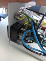
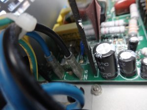
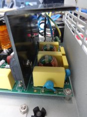
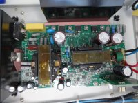
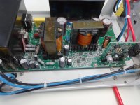
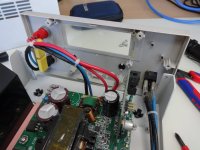
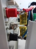
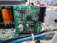
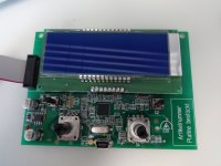
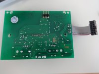
teardown
conclusion
pro:
- fulfils all initial power supply criteria
- set output is within accuracy
- good design, lay out, quality components
- fast first contact response
contra:
- output is not switched of completely
- measured value is up to 0.4 V lower than output voltage
- second digit after . of voltage is always 0 and not settable (it should not be displayed in this case)
- second digit after . of voltage is always 0 and does not show measured value (the actual measured data is precise enough to show this digit)
- can skip fast knob turns
- USB cable does no fit in port because of the indent
- information in english programming manual missing
- small mistakes in programming manual
- can not be calibrated by end user, and vendor only calibrates if under warranty
- no contact support

