Table of Contents
The U2 is a USB power meter and tester.
Overview
Features
It is full of features and makes it the most complete USB power meter I known of:
- wide voltage and current range, with high precision: 0-24 V DC @ 0.00001 V, -5-5 A @ 0.00001 A (covers all standardized USB voltages and currents)
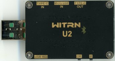
- multiple USB inputs (USB 3.1 type-A plug, micro-USB, USB-C) and outputs (USB 3.1 type A socket, USB-C)
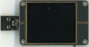
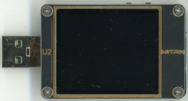
- large (1.77 in / 4.5 cm) clear (can use large fonts) LCD screen (160*128 pixels)
- can detect charger compliance/profile: Apple (5V @ 2.4A, PD), Samsung (5V @ 2.0A, AFC), USB Battery Charging (BC1.2 DCP), Qualcomm Quick Charge (QC 2.0, QC 3.0), USB Power Delivery (PD 2.0, PD 3.0, E-Marker), Huawei (FCP, SCP), MTK (PE1.1, PE2.0), OPPO (VOOC, DASH, Super, FLASH)
- external power input: to not affect the current measurement, the device can be powered using the micro-USB HID plug. This also allows to measure voltages under 4 V (the minimum required if you power using the normal USB port)
- computer interface to read the measured values: USB HIB (micro-USB port which also can externally power the device), and Bluetooth (U2p version)
Resources
The manufacturer is called WITRN. The device was first called WEB-U2, but now they registered the trademark/brand Qway to fight piracy.
You can buy the device from the official store witrn on taoboa.
The software also points to the probably authorized re-seller GUZt.
The manual warms about the clones from ATORCH.
The official website is rather empty.
It only points to the user guide and software (with broken link).
Instead they recommend to follow the QQ group 313755927.
Here links I could gather to get the latest version of:
There is also this thorough review and another with a lot of information in the comments.
Hardware
There are several versions of the hardware.
WITRN U2 104083
This is the first device I bought from the HiDANCE store, and seems to be a clone.
The original manufacturer blocked this device.
After flashing firmware version 5.5, the display would just show 104083 ERR, and the device would not work anymore.
Moreover it was not possible to re-flash it anymore.
Thus don't install firmware version 5.5 of later if you have a device with serial 104083, else you will brick it.
Software version 4.0 or later also do not work with this device. You need to use version 3.0.
This device can still be used to measure voltage and current, but since there is no update anymore it will not be able to be used to detect charger profiles.
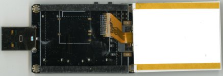
There is also a footprint for an Bluetooth adapter behind the screen, but it was not placed yet (the software was probably not ready).
I read out the FRAM (where the settings are stored) but did not find the serial number in there. I also cleared it to confirm the serial is not stored in the FRAM, but in the firmware. Sadly the firmware is read protected.
Debug header pinout:
  _________
__|8 6 4 2|
|9 7 5 3 1|
-----------
- SWDIO (SWD, STM32F072 pin 34/PA13)
- SDA (I²C, with FRAM at 0x50)
- SWCLK (SWD, STM32F072 pin 37/PA14)
- GND
- GND
- VDD
- VDD
- SCL (I²C, with FRAM at 0x50)
- nRST (SWD, STM32F072 pin 7/NRST, you must connect under reset since SWD is disable after boot)
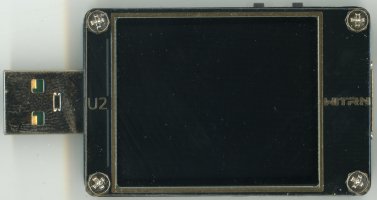
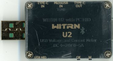
WITRN U2 V2.0
Because the clone got bricked, I got a genuine replacement.
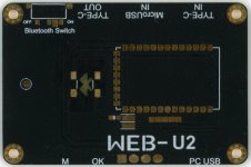
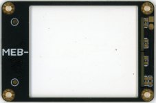
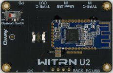
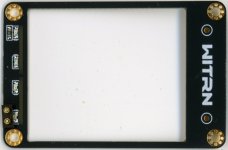
A Bluetooth module could be placed on the front side of the bottom board. The front board could also be light bz LEDs from the back side.
Qway U2p
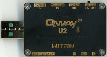
The U2p version is a variant of the U2 with 4 button instead of 2, and a switch to enable Power Delivery probing
Finally it was also possible to get a version with Bluetooth and some light next to the USB input (not sure when it is on though)
Board
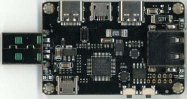
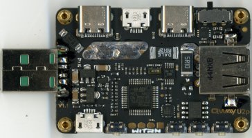
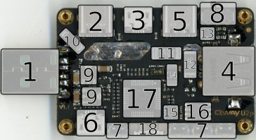
Here a list of the components present on the Qway U2p V1.1 board:
- input USB 3.0 type A plug
- input USB type C socket
- input USB type micro-B socket
- output USB 3.0 type A socket
- output USB type C socket
- data USB type micro-B socket, USB HID connection to the computer to read the measurements and flash the firmware
- 4 button to interact with the interface (back, ok, previous, next)
- PD switch to enable USB-C Power Delivery triggering
- Micro One ME6203 3.3V LDO voltage regulator: one for the USB type A input, the other for the USB HID micro-B input to not affect the measurements
- input diode protection: not in-line, but shorting GND to VBUS when GND > VBUS
- R012F shunt resistor (12 mOhm): to measure the current
- 5R10 shunt resistor (5.1 Ohm): which can be switched in line to measure low currents
- ON FUSB302 (marked PBAB) Programmable USB Type-C Controller with PD: this gets enabled by the PD switch
- TI INA226 current and power monitor: this makes the measurements
- NXP MMA8452Q accelerometer: to automatically rotate the display
- Fujitsu MB85RC16 I²C FRAM: to store the settings and energy measurements
- ST STM32F072CBT6 ARM Cortex-M0 micro-controller: the brain of the device
- UART pins: to connect to the AT-09/HM-10 Bluetooth module (with TI CC2541 chip). pinout, beginning with square pin: 3.8V GND RX TX
Software
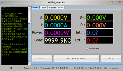
Here a couple of notes about the PC software (for Windows).
The software is in Chinese, but you can change it by translating the words in the lang.ini file.
Here the english lang.ini (works for versions 4.0, 4.1, 4.4).
When started, the software will query http://www.witrn.com/updata/U2_NewVersion.pdf to get the latest version information.
This is not a pdf. I think this is just to pass firewall (just like they use HTTP without SSL).
This URL will return a short binary string, for example 0x44 0x67 0x25 0x11 0x12 0x12 0x13 0x21:
0x44: Software version 4.40x67: U2 Firmware version 6.70x25: X Firmware version 2.50x11: C3 Firmware version 1.10x12: C1 Firmware version 1.20x12: C0 Firmware version 1.20x13: C0s Firmware version 1.30x21: A0 Firmware version 2.1
If will also query http://www.witrn.com/updata/U2_ad.pdf, which is again not a pdf, but the text to display on the left side.
Using the Network upgrade it will also download the Firmware for the U2 at http://www.witrn.com/updata/U2_FW_NEW.pdf and U2p at http://www.witrn.com/updata/U2_4KEYS_FW_NEW.pdf (raw binaries)
Communication
USB HID
When connected to USB, it appears as an HID (Human Interface Device).
When powered while pressing on the OK button, it will boot in the DFU (Device Firmware Upgrade) mode, which allows flashing the firmware.
But it is still an HID, and does not use the DFU profile specified by USB.
I've partially reversed the HID communication:
- the messages exchanged are 64 bytes long
- the host (e.g. software) starts by sending a message. Here an example of message sent (captured from the software):
"\xff\x55\x58\x8a\x13\x79\x06\x57\x1a\x01\x0a\x02\x00\x00\x00\x00" \
"\x5e\x00\x00\x00\xff\x55\x2f\xb2\x8b\xdc\x5a\xd4\x1a\x2c\xa4\x00" \
"\xa4\x40\x00\x00\x00\x00\x00\x00\x00\x00\x0e\x74\x21\x4f\x40\x75" \
"\x23\x19\x40\x75\xcc\x01\x01\x00\x02\x04\x00\x00\x5e\x00\xe7\x06";
- this will cause the device (e.g. U2) to send measurements. Since it will only send a couple of messages, keep sending the message every couple of milliseconds (can be the same). Here an example measurement reply:
ff 55 13 b4 7f bf 50 ef 1a 2c d7 63 a0 40 0e 74 da 39 0e 74 da 39 0e 74 da 39 bb dd 08 3b 33 33 53 40 74 a8 6d 3c fe 98 f7 41 d2 34 91 c2 14 ae a0 40 0e 74 da 39 00 00 00 00 00 00 00 00 16 ae
here how to decode the measurements:
| index | byte(s) | format | meaning |
|---|---|---|---|
| 0-1 | ff 55 | constant | probably a fixed header |
| 2 | 13 | integer | number of second |
| 3 | b4 | integer | super fast incrementing number (but not related to other bytes) |
| 4 | 7f | integer | fast incrementing number (but not related to other bytes) |
| 5 | bf | integer | incrementing number (but not related to other bytes) |
| 6 | 50 | integer | 1/100th of byte 5 |
| 7 | ef | integer | slow incrementing number (but not related to other bytes) |
| 8-9 | 1a 2c | constant | separates timing form measurement values |
| 10-13 | d7 63 a0 40 | float | VBUS voltage, in V (e.g. 5.0122 V) |
| 14-17 | 0e 74 da 39 | float | VBUS current, in A (e.g. 0.0004 A) |
| 18-21 | 0e 74 da 39 | float | VBUS current, in A (seems the same as previous current) |
| 22-25 | 0e 74 da 39 | float | VBUS current, in A (sometimes slightly different for the other values, but I don't know why) |
| 26-29 | bb dd 08 3b | float | VBUS power, in W (e.g. 0.0021 W ) |
| 30-33 | 33 33 53 40 | float | D+ voltage, in V (e.g. 3.3000 V) |
| 34-37 | 74 a8 6d 3c | float | D- voltage, in V (e.g. 0.0145 V) |
| 38-41 | fe 98 f7 41 | float | In temperature (internal), in °C (e.g. 30.95 °C) |
| 42-45 | d2 34 91 c2 | float | Ex temperature (external, from IN Micro-USB probe), in °C (e.g. -72.60 °C, because not connected) |
| 46-49 | 14 ae a0 40 | float | VBUS voltage (differs from first value, but I don't know how), in V (e.g. 5.0212 V) |
| 50-53 | 0e 74 da 39 | float | VBUS current (sometimes slightly different for the other values, but I don't know why), in A (e.g. 0.0004 A) |
| 54-61 | 00 00 00 00 00 00 00 00 | constant | seems always 0 |
| 62 | 16 | integer | checksum (addition of bytes 8-61) |
| 63 | ae | integer | checksum (addition of bytes 0-61) |
There are other messages to get the device's serial number and firmware version, but I did not reverse those.
I've implemented a software (C program for Linux) to read to measurements over USB and output it as CSV. You can find it in the git.
Bluetooth Serial
The Qway has an optional Bluetooth module. This allows getting the measurement without physical connection (e.g. the USB HID port). You can use the Android app to communicate with the device.
I reversed the protocol so I can get the raw data myself.
Scan for Bluetooth (Low Energy) devices and look for one named QWAY_U2_xxx, with xxx being the device's serial number.
There is no need to pair with the device.
You can directly connect to it.
Data is then exchanged using the GATT characteristic 0000ffe1-0000-1000-8000-00805f9b34fb.
On the hardware side, the Bluetooth board uses a HM-10 module (with TI CC2541 chip) to send the measurement over Bluetooth Low Energy. The main board is connected to the Bluetooth board using spring contacts and uses UART to communicate with the module (at 115200 bps).
First send the message 0xf1 0x01 0x00 0x00 0x00 0xfe to get device information.
The device will reply with a message using the following format (the bytes use little endian order):
0xf1 0x01 0x30 0x31 0x31 0x33 0x33 0x37 0x67 0x14 0x00 0x00 0x00 0x32 0x00 0x00 0x00 0x00 0x03 0x00
| index | byte(s) | format | meaning |
|---|---|---|---|
| 0-1 | f1 01 | constant | header |
| 2-7 | 30 31 31 33 33 37 | ASCII | device's serial (here 011337) |
| 8 | 67 | nibbles | firmware version (here 6.7) |
| 9-12 | 14 00 00 00 | uint32 | number of times the device has run (here 20) |
| 13-14 | 32 00 | uint16 | current threshold for recording, in mA (here 50 mA) |
| 14-17 | 00 00 00 00 | float | energy recorded for this group, in Wh (here 0). note: the data overlaps with the previous field |
| 18 | 03 | uint8 | current recording group number (here 3 + 1 = 4) |
| 19 | 00 | constant | trailer |
The device then sends measurements for a bit of time. To keep the device sending measurements, send periodically the following message:
0xf1 0x02 0x00 0x00 0x00 0xfe
A complete measruement set is comprised of 5 messages. But each message includes the voltage and current measurements, providing a higher time resolution for these values.
| index | byte(s) | format | meaning |
|---|---|---|---|
| 0-1 | fe 01 | constant | header form message 1 |
| 2-5 | float | VBUS voltage, in V | |
| 6-9 | float | VBUS current, in A | |
| 10-13 | float | D+ voltage, in V | |
| 14-17 | float | D- voltage, in V | |
| 18 | uint8 | current recording group number, add 1 | |
| 19 | 00 | constant | trailer |
| index | byte(s) | format | meaning |
|---|---|---|---|
| 0-1 | fe 02 | constant | header form message 2 |
| 2-5 | float | VBUS voltage, in V | |
| 6-9 | float | VBUS current, in A | |
| 10-13 | float | internal temperature, in °C | |
| 14-17 | float | external temperature (from USB probe), in °C | |
| 18 | uint8 | current recording group number, add 1 | |
| 19 | 00 | constant | trailer |
| index | byte(s) | format | meaning |
|---|---|---|---|
| 0-1 | fe 03 | constant | header form message 3 |
| 2-5 | float | VBUS voltage, in V | |
| 6-9 | float | VBUS current, in A | |
| 10-13 | uint32 | on time, in s | |
| 14-17 | uint32 | recording time, in s | |
| 18 | uint8 | current recording group number, add 1 | |
| 19 | 00 | constant | trailer |
| index | byte(s) | format | meaning |
|---|---|---|---|
| 0-1 | fe 04 | constant | header form message 1 |
| 2-5 | float | VBUS voltage, in V | |
| 6-9 | float | VBUS current, in A | |
| 10 | int8 | acceleration value, X-axis | |
| 11 | int8 | acceleration value, Y-axis | |
| 12 | int8 | acceleration value, Z-axis | |
| 14-17 | uint32 | recording time, in s | |
| 18 | uint8 | current recording group number, add 1 | |
| 19 | 00 | constant | trailer |
| index | byte(s) | format | meaning |
|---|---|---|---|
| 0-1 | fe 01 | constant | header form message 1 |
| 2-5 | float | VBUS voltage, in V | |
| 6-9 | float | VBUS current, in A | |
| 10-13 | float | recorded charge, in Ah | |
| 14-17 | float | recorded energy, in Wh | |
| 18 | uint8 | current recording group number, add 1 | |
| 19 | 00 | constant | trailer |
when the device is unresponsive, the Bluetooth app sends the following message (with some data instead of the 00):
0xf1 0x03 0x00 0x00 0x00 0xfe
I did not take time to reverse this since I got the measurements I was looking for.
I've implemented a software (C program for Linux) to read to measurements over Bluetooth and output it as CSV. You can find it in the git.

