Table of Contents
The Linear remote control solution from the MegaCode series was used in the facility complex I was living for a short while, and I wanted to know how secure it is. Thus I reverse engineered it.
At 31c3 I gave a short talk about how to clone and record codes. In episode #004 I presented how the transmitting part works, and how to clone the radio remote controls. In episode #005 I presented how the receiving part works, so to record codes and analyze them.
transmitter
ACT-34B
The main target is the ACT-34B from the Linear MegaCode series. The ACT-31B is the same as the ACT-34B but with only one button.
- FCC-ID EF4 ACP00872 (archive)
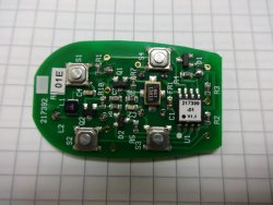
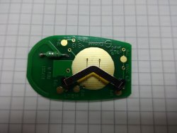
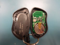
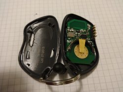
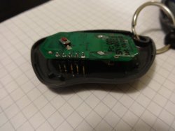
internal pictures:
It uses a PIC12C508. The PICkit2 programmer does not support the PIC12C family because it's EPROM based and requires higher voltage. By accidentally reading the code it erased it. But code protection was probably used. This chip can also come as One Time Programmable, and might be factory programmed.
318LIPW1K
The flashable alternative to the ACT-34B is the 318LIPW1K from the Transmitted Solution Monarch series.
- FCC-ID SU7 318LIPW1K (archive)
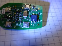
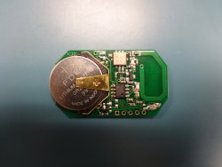
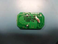
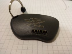
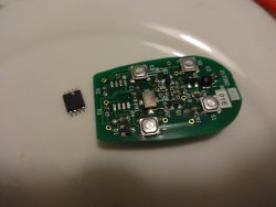
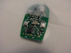
internal pictures:
It uses a PIC12F635. The PICkit2 programmer does support the PIC12F family because it's flash based. But code and data protection were.
receiver
MDR
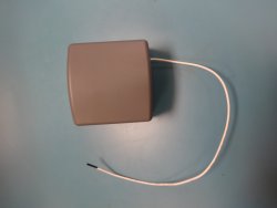
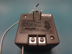
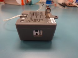
The main target is the MDR from the Linear MegaCode series.
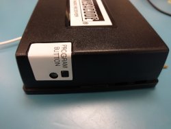
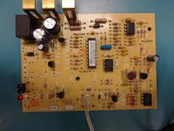
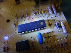
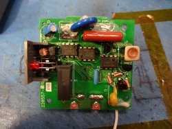
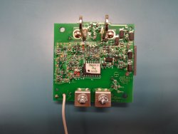
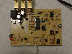
internal pictures:
It uses a PIC12C54A. The PICkit2 programmer does not support the PIC16C family because it's EPROM based and requires higher voltage. But code protection is probably used. This chip can also come as One Time Programmable, and might be factory programmed.
MDR-U
The main target is the MDR-U from the Linear MegaCode series.
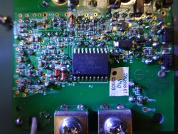
internal pictures:
It uses a PIC12C54A. The PICkit2 programmer does not support the PIC16C family because it's EPROM based and requires higher voltage. But code protection is probably used. This chip can also come as One Time Programmable, and might be factory programmed.
protocol
The MegaCode protocol is partially specified in the FCC documents MegaCode1 (backup) and MegaCode2 (backup).
It uses Amplitude Modulation (AM) on 318MHz. There are two levels: on and off. The transmission uses 24 bit frames and 1 blank cell. Each is 6 ms long. Within each bit frame a 1 ms pulse is send. The pulse is either in the first or second half within the bit frame (after 2 or 5 ms). This defines if the bit is a 0 or 1. The first bit frame is used as sync frame and is always a 1. It is followed by 20 system code bits and 3 data bits.
software defined radio
This signal can be recorded using a software defined radio (SDR). I used the inexpensive USB DVB stick RTL-SDR.
First find the exact frequency at which the remote transmits using an FFT software, such as sdrangelove. Use this frequency to record and demodulate the signal using rtl_fm:
rtl_fm -f 317.962M -M am megacode.pcm
The recorded data can be view in audio editing tools such as audacity by importing it as raw data, 24kHz, mono, 16 bits little endian.
The code can also be extracted using decode.rb
./decode.rb megacode.pcm
This decodes the transmissions and lists the 3 bytes values.
# egdes: 0
# pulses: 0
# groups: 1 (1)
# transmissions: 0
# values: 0
# egdes: 1822
# pulses: 167
# groups: 9 (24, 24, 23, 13, 10, 24, 24, 24, 1)
# transmissions: 5
# values: 5
values:
- value: 13178818 (0xc917c2), system code: 598776 (0x922f8), databits: 2 (0x2)
- value: 13178818 (0xc917c2), system code: 598776 (0x922f8), databits: 2 (0x2)
- value: 13178818 (0xc917c2), system code: 598776 (0x922f8), databits: 2 (0x2)
- value: 13178818 (0xc917c2), system code: 598776 (0x922f8), databits: 2 (0x2)
- value: 13178818 (0xc917c2), system code: 598776 (0x922f8), databits: 2 (0x2)
transmitting
318LIPW1K
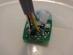
The 318LIPW1K can be flashed using a PICkit2 micro-controller. The schematic describes how the micro-controller is connected.
A pin header can be soldered on the board:
The firmware is available in git. You can define the code to transmit in EEPROM.
ACT-34B
I de-soldered the PIC12F508A micro-controller and replaced it with a pin compatible (slimmer) PIC12F1840:
The firmware is available in git. The two right buttons are used to send codes defined in the source. I planned to use the two left buttons to brute force codes but did not finish the implementation.
receiving
MDR
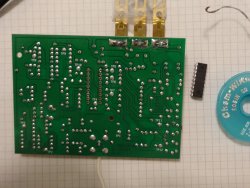
I de-soldered the PIC16C54A micro-controller and replaced it with a pin compatible PIC16F1847:
The schematic describes how the micro-controller is connected.
The firmware receiving and recording codes is available in git. How it works and how to use it further is described in the README. All codes are read out over I²C when the board is powered up. They can be recorded/transferred on the PC using a logic analyzer.
The original way the codes are recorded by the device in the EEPROM is described in the README
MDR-U
The MDR-U is basically the same as the MDR. The board is different, but the peripheral and connections around the micro-controller. It uses more surface mount components. It is powered through the mains (CAUTION: neutral is used as 0V).
Same as for the MDR, I de-soldered the PIC16C54A micro-controller and replaced it with a pin compatible PIC16F1847 (SOIC version). The firmware is the same as the MDR.
RF module
aaronsp777 implemented a receiver using a generic 315 MHz module, and an Arduino.

