This is an old revision of the document!
Table of Contents
these are my notes on how I dump SPI flash.
SPI flash
Since flash uses kind of another technology, it is often hard or expensive to add flash memory in integrated circuits (IC), mainly micro-controller (MCU). Thus MCU have either very limited flash size (< 1 MB), or you have to provide it externally. Externally dedicated flash is very common and inexpensive. Some system on a chip (SoC) even just add the flash die next to the MCU die (this is called package in/on package).
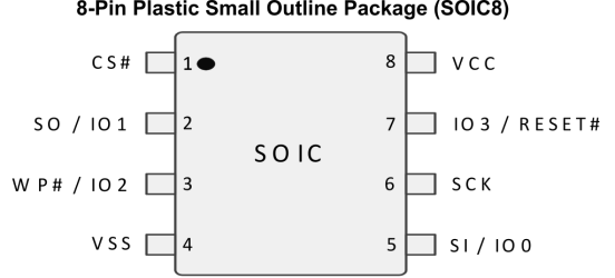
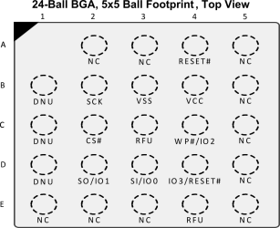
The most common package for flash is SOIC-8 (surface mount, 8 pins, 1.27 mm pin pitch, 200 mil wide body). More compact alternatives are WSON/LGA (without external lead) and BGA (allowing more pins underneath). Whenever you find such a chip with 25 on the top marking, it is very probably a flash chip.
The most common interface is Serial Peripheral Interface (SPI). It allows extremely fast transfer rates (clock frequency > 100 MHz) and is supported by most MCU. For even faster communication, high-end chips even provide quad output support (QSPI).
The pinout is (almost) always the same to provide interoperability. The difference between models is mainly the size (obviously), and features (i.e. speed).
dumping tools
chip-off
By far the easiest method is to de-solder the chip and place it in a dedicated programmer. The only disadvantage is that you will have to de-solder and re-solder the chip every time you want to read or write it.
CH341A
The cheapest, and crudest, way to read/write SPI flash is using a CH341A based programmer. You can find them for less than $3.
Solder the SPI flash to a DIP-8 adapter board, and place it in the ZIF socket (Zero-Insertion-Force). Insert it as depicted on the side for the 25xx (furthest away from the lever, with pin 1 notch facing the lever). To avoid soldering the chip on an adapter board, use sockets with spring contacts (the contacts need to be clean for it to work well). Be sure the jumper shorts pin 1 and 2 on the side (shorting pins 2 and 3 switched the CH341A to UART mode).
As software we will use ch341prog. Verify if the chip is detected correctly, then read the memory out:
ch341prog --info

Device reported its revision [4.03]
Manufacturer ID: ef
Memory Type: 4016
No CFI structure found, trying to get capacity from device ID. Set manually if detection fails.
Capacity: 16
Chip capacity is 4194304 bytes


ch341prog --read spi.bin

...
Read started!
Limitations:
- slow speed (128 kbyte/s)
- no power supply protection (if you insert the chip the wrong way around, you will fry it since VCC and GND/VSS get switched)
- operating voltage is 5V (you can modify it to 3.3V by lifting top right pin 28, put tape over the pad, connect pin to C4 on the bottom and middle pin of voltage regulator AMS1117). Most flash chip operate at 3.3V, and while 5V is outside of the maximum rating, they still seem to support it (at least for a short time)
- to support 1.8V flash chips, interpose an adapter board with level shifter


